
Understanding the Current Across Inductor in RLC Circuit Analysis
Introduction to RLC Circuits
- RLC circuits are electrical circuits with resistors, inductors, and capacitors connected in series or parallel, characterized by voltages and currents described by second-order differential equations.
- These circuits function as filters, amplifiers, or oscillators in integrated circuits, using resonance and damping properties.
- RLC circuits contain two energy storage elements: inductor and capacitor, requiring two initial conditions and second-order differential equations.
- The circuit elements collectively determine the behavior of RLC circuits, including series RLC circuits and parallel RLC circuits.
Components of RLC Circuits
- Resistors resist current flow causing voltage drops, with resistance independent of signal frequency.
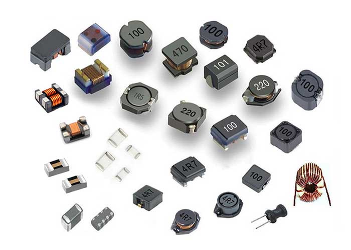
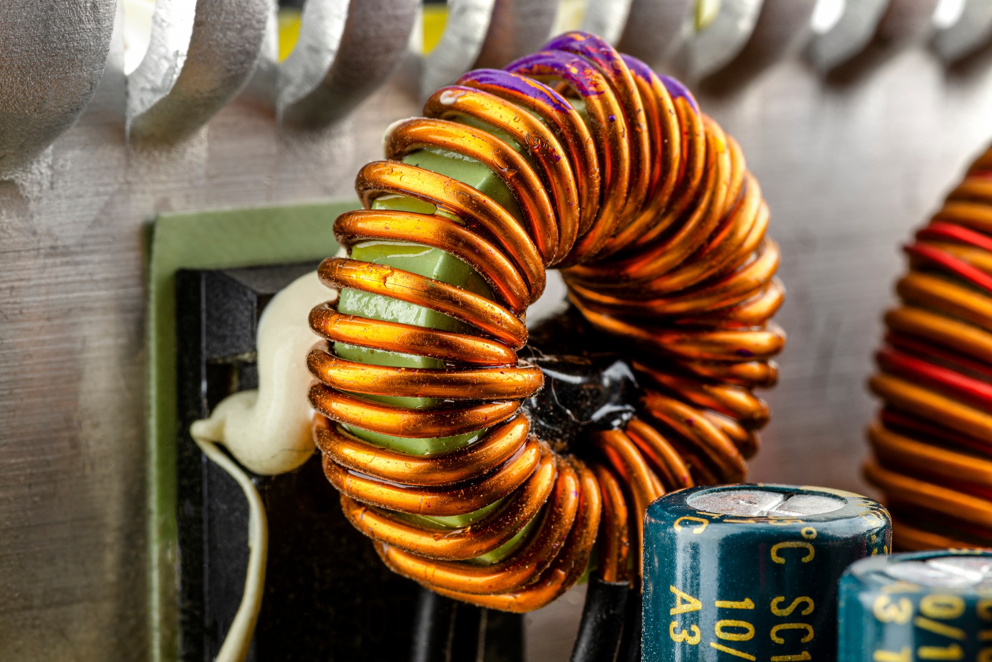
- Inductors store energy in a magnetic field and oppose current changes via frequency-dependent inductive reactance.
- Capacitors store energy in an electric field and oppose voltage changes via frequency-dependent capacitive reactance.
- The three circuit elements can be arranged in various topologies, with series and parallel being the simplest.
Types of Circuits
- Series RLC circuits have R, L, and C connected in a single path with constant current and varying voltages; total voltage is the vector sum of voltages.
- Parallel RLC circuits have constant voltage across elements with varying currents; total current is the vector sum of branch currents.
- Series circuit impedance: ( Z = \sqrt{R^2 + (X_L – X_C)^2} ), where (X_L) and (X_C) are frequency-dependent reactances.
- Parallel circuit impedance is the reciprocal of series impedance; admittance (1/Z) simplifies calculations in parallel circuits.
RLC Circuit Analysis
- RLC circuit analysis combines resistance, inductance, and capacitance into one circuit, considering the phase difference between voltage and current.
- The overall circuit reactance depends on the magnitudes of inductive reactance (XL) and capacitive reactance (XC).
- Series RLC circuits are second-order circuits due to two energy storage elements: L and C.
- The combined RLC circuit behaves similarly to series RL and RC circuits but requires total reactance calculation.
Phasor Diagram
- Phasor diagram combines the three voltage phasors vectorially for the series RLC circuit, with current as the common reference vector.
- Voltage vectors are drawn relative to the current vector at their respective phase angles.
- The resulting vector sum represents the total voltage across the circuit elements.
- The phasor diagram visually represents the relationship between voltages in the circuit.
Series RLC Circuit
- Current flowing through a series RLC circuit is the same for all three components.
- Inductive reactance (XL) and capacitive reactance (XC) vary with supply frequency (ƒ).
- Voltage drops across R, L, and C are out-of-phase with each other.
- Source voltage amplitude equals the vector sum of voltages across the three components with current as reference.
Parallel RLC Circuit
- In a parallel RLC circuit, voltage across each component is the same, and currents through each component are out-of-phase.
- The circuit’s impedance is determined by the combination of resistance, inductive reactance, and capacitive reactance.
- Parallel RLC circuits can be used as filters, amplifiers, or oscillators, depending on the application.
- The circuit’s behavior is characterized by its resonant frequency and damping factor.
Voltage Across Components
- Voltages across the resistor, inductor, and capacitor are related to the current flowing through them.
- The voltage across the resistor is in-phase with the current, while the voltage across the inductor leads the current by 90°, and the voltage across the capacitor lags the current by 90°.
- The voltage across each component can be calculated using Ohm’s law and the circuit’s impedance.
- The voltage across the inductor and capacitor can be used to determine the circuit’s resonant frequency.
Resonance in RLC Circuits
- Resonance occurs when inductive reactance equals capacitive reactance: ( X_L = X_C ).
- Resonant frequency ( f_0 = \frac{1}{2\pi \sqrt{LC}} ) minimizes impedance and maximizes current.
- At resonance, the RLC series circuit behaves like a purely resistive circuit with impedance equal to resistance.
- Resonance is critical in applications like radio tuners for frequency selection and signal clarity.
Power in RLC Circuits
- Power delivered varies with frequency due to phase angle ( \phi ) between voltage and current.
- Power factor is ( \cos \phi = \frac{R}{Z} ), reaching 1 at resonance when voltage and current are in phase.
- Average power is ( P{ave} = I{rms} V_{rms} \cos \phi ), maximized at resonant frequency.
- Energy oscillates between inductor and capacitor; only the resistor dissipates power as heat.
Impedance in RLC Circuits
- Impedance in an RLC circuit combines resistance, inductive reactance, and capacitive reactance.
- Inductive reactance (XL) and capacitive reactance (XC) partially cancel due to opposite effects.
- Voltage across inductor (VL), capacitor (VC), and resistor (VR) have distinct phase relationships with current.
- Impedance Z is calculated as ( Z = \sqrt{R^2 + (X_L – X_C)^2} ), affecting total voltage and current.
RLC Circuits Applications
- RLC circuits are used in filter circuits, oscillator circuits, and other applications where frequency selection is crucial.
- They are also used in radio receivers, TVs, and other communication devices for band-pass filtering.
- RLC circuits can be used to design narrow band filters or wide band filters, depending on the application.
- The circuit’s resonant frequency and damping factor can be adjusted to achieve the desired bandwidth.
Conclusion
- RLC circuits are essential in electrical engineering, and understanding their behavior is crucial for designing and analyzing circuits.
- The circuit’s components, including resistors, inductors, and capacitors, determine its behavior and characteristics.
- RLC circuits can be used in various applications, including filter circuits, oscillator circuits, and communication devices.
- The circuit’s resonant frequency and damping factor are key parameters that can be adjusted to achieve the desired performance.
Future Developments
- Future developments in RLC circuits may include the use of new materials and technologies to improve their performance and efficiency.
- The use of RLC circuits in emerging applications, such as renewable energy systems and electric vehicles, may also become more prevalent.
- Advances in simulation and modeling tools may also enable the design and analysis of more complex RLC circuits.
- The development of new circuit topologies and configurations may also lead to improved performance and efficiency in RLC circuits.
Common Applications and Industries
RLC circuits play a vital role in various applications and industries due to their unique ability to control and manipulate alternating current signals through resonance and filtering effects. They are widely used in:
- Communication Systems: RLC circuits serve as band-pass filters and oscillators in radio receivers and television sets, enabling the selection of specific frequencies from a broad range of radio waves. This allows for clear tuning to desired channels while blocking unwanted signals.
- Signal Processing: In filter circuits, RLC components help block signals close to undesired frequencies and allow signals at the resonance frequency to pass, making them essential in audio and data processing devices.
- Power Electronics: RLC circuits are used in power supplies and converters to smooth out voltage fluctuations and reduce noise, enhancing the reliability and efficiency of electrical systems.
- Instrumentation and Measurement: Due to their precise frequency response, RLC circuits are employed in oscillators and sensors to generate or measure specific frequencies and signals.
- Automotive and Aerospace: These circuits contribute to the design of control systems and communication modules, where stable and selective frequency handling is crucial.
- Renewable Energy Systems: Emerging applications include their use in managing power quality and filtering in renewable energy inverters and electric vehicles.
Across these industries, the ability of RLC circuits to store energy alternately in the magnetic field surrounding inductors and the electric field of capacitors, combined with their frequency-dependent impedance, makes them indispensable components in modern electrical and electronic systems.
Future Trends in RLC Circuits
As technology advances, RLC circuits continue to evolve, finding new applications and improved performance through innovative materials and design techniques. Future trends in RLC circuits include:
- Integration with Emerging Technologies: RLC circuits are increasingly being integrated into renewable energy systems and electric vehicles, where efficient power management and signal processing are critical.
- Advanced Materials: The development of novel materials with superior electrical properties, such as high-temperature superconductors and nanomaterials, promises to enhance the performance of inductors and capacitors within RLC circuits.
- Miniaturization and Integration: Continued miniaturization of components allows for more compact and efficient integrated circuits, enabling RLC circuits to be embedded in a wider range of devices, including wearable technology and IoT devices.
- Improved Simulation and Modeling: Advances in simulation software enable more accurate modeling of RLC circuits, including parasitic effects and electromagnetic coupling, leading to optimized designs with better frequency response and reduced energy loss.
- New Circuit Topologies: Research into alternative circuit configurations and hybrid designs aims to improve bandwidth, selectivity, and damping characteristics, catering to specialized applications in communications and signal processing.
These future developments will expand the capabilities and applications of RLC circuits, maintaining their essential role in modern electrical engineering and electronic systems.