Understanding the Working Principle of Inductor Circuit for Efficiency
Introduction to Inductors
Inductors are passive components and passive two-terminal electrical components that store energy in a magnetic field when electric current flows through them—they are key elements in electronic circuits, used in power supply circuits, filters, and tuned circuits. An inductor stores energy in its magnetic field, which is fundamental to its operation.
The magnetic field created by current flowing through the coil induces a voltage opposing changes in current, according to Faraday’s and Lenz’s laws, which is crucial for understanding inductor behavior in ac circuits. This process is called electromagnetic induction.
Inductors have inductance measured in henries (H), often enhanced by a magnetic core made of iron or ferrite to increase the magnetic field and improve efficiency in power circuits. Self inductance is the property of an inductor that causes it to oppose changes in current flowing through it.
Inductors are used to block ac current, filter frequencies, and tune circuits for radio and TV receivers, showcasing their versatility in various applications.
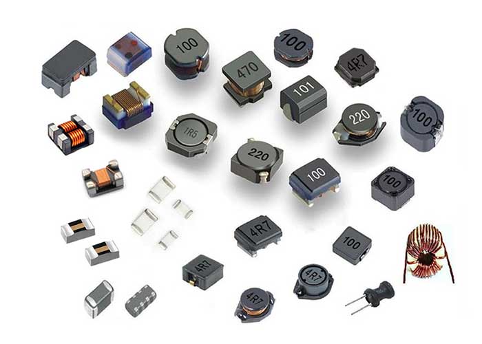
Inductor construction and types, including air core inductors and iron core inductors, play a significant role in determining their magnetic properties and suitability for specific applications. An inductor consists of a coil of wire, often wound in multiple layers or turns, which determines its inductance and behavior in electronic circuits.
Inductor Construction and Types
- Inductor construction involves a coil of wire, often wound around a magnetic core, which can be made of ferrite, iron, or air, each affecting the magnetic flux density and inductive characteristics. Inductors can be constructed using either solid wire or multi-stranded wire; using solid wire increases resistance and reduces efficiency compared to multi-stranded wire, especially in high-frequency applications.
- Inductor cores are used to categorize inductors based on their core material, such as air core, ferrite core, or iron core, with each type influencing the inductor’s energy storage and electrical parameters. The type of core material used, such as powdered iron core inductors or ferrite core inductors, influences the magnetic flux linkage and voltage drop in the inductor coil.
- Air core inductors are constructed without a magnetic core, using only the coil of wire, which results in lower magnetic flux density compared to iron core inductors but provides excellent magnetic stability and minimal losses. Air core inductors are commonly used in high-frequency and RF circuits due to these properties.
- Ferromagnetic core inductors, which use materials like iron or ferrite, offer reduced magnetic flux leakage and improved stability, enhancing high-frequency performance in various circuits and applications.
- Powdered iron core inductors are valued for their versatility and performance in electronic circuits. A powdered iron core inductor features distributed air gaps within the core material, providing stable inductance and minimizing core losses, making them suitable for power electronics and RF applications.
- Inductor types also include variable inductors, which allow for adjustments in the magnetic field and are used in tuned circuits and resonant circuits.
- The quality factor (q factor) of an inductor is crucial in determining its efficiency and suitability for various applications, including power supplies and signal filtering.
Inductor Coil and Core Material
- The inductor coil is the heart of the inductor, where electric current flows and generates a magnetic field, with the core material playing a significant role in enhancing the magnetic flux. It is important that the coil windings are arranged in the same direction to ensure uniform magnetic flux and optimal electromagnetic behavior.
- Magnetic core materials, such as ferrite or iron, are used to increase the magnetic field and improve the inductor’s efficiency, especially in power circuits and electronic circuits. The dc resistance of the coil also affects the steady-state current flow and overall efficiency, particularly in applications like wireless charging coils and tuning circuits.
- The number of turns in the coil and the core material used affect the inductor’s impedance and its ability to store energy in the magnetic field. The maximum value of current or emf in the coil is reached during transient conditions or at steady state, which is important for circuit design and safety.
- Ferrite core inductors are commonly used in high frequency circuits due to their high magnetic permeability and low energy dissipation.
- The core material’s magnetic properties, such as its permeability and saturation point, are critical in determining the inductor’s performance and suitability for specific applications.
Inductor Circuit Analysis and Applications
Inductor circuit analysis involves understanding the behavior of inductors in ac circuits, where they play a key role in energy storage, filtering, and tuning applications. In an ac circuit, the inductor’s response differs from that in a dc circuit due to the alternating nature of the current, which leads to unique phenomena such as reactance and resonance. A circuit diagram is often used to visually represent how inductors behave in both AC and DC circuits, helping to illustrate the relationships between current, voltage, and the inductor’s properties. The inductor’s impedance is frequency-dependent, increasing with higher frequencies, which is critical for analyzing circuit performance, especially near resonance.
Inductors are used in power circuits to filter and regulate the voltage, ensuring a stable dc current output, and in electronic circuits to tune and filter frequencies. When the current through an inductor changes, an induced voltage is generated that opposes the change, a result of electromagnetic induction—the fundamental principle behind inductor operation. This induced voltage, also known as electromotive force (emf), can have a positive value or negative value depending on whether the current is increasing or decreasing, respectively. The emf generated in the inductor resists changes in current, and this opposition is more pronounced at high frequencies due to the increased inductor’s impedance, while at low frequencies and in low frequency applications, the impedance is lower, allowing more current to pass.
The inductor’s ability to store energy in its magnetic field makes it an essential component in resonant circuits and tuned circuits, such as those used in radio frequency applications. The magnetic field generated by the inductor is central to its operation, and the design of the inductor can influence how magnetic fields are concentrated and managed within a circuit, affecting performance and electromagnetic interference (emi). As an ac voltage is applied to an inductor, the current rises from zero, but due to the induced emf, there is a phase lag between the voltage and current. At high frequencies, the inductor blocks more current, making it suitable for filtering out high-frequency signals, while at low frequencies, it allows more current to pass, which is useful in low frequency and power supply applications.
Inductors are also used to protect circuits from electromagnetic interference (emi) and to prevent mechanical vibration in sensitive equipment.
In ac circuits, inductors oppose changes in current flow, causing a voltage drop, which can be used to filter out unwanted frequencies and improve signal quality. This opposition is due to the induced voltage created by electromagnetic induction, and the direction of the induced emf—whether it is a positive value or negative value—depends on the direction of the current change.
Energy Storage and Mutual Inductance
- Inductors store energy in their magnetic field when current flows through the coil, with the amount of stored energy depending on the inductor’s inductance and the current flowing through it. This stored energy is a form of electromagnetic energy, resulting from the conversion of electrical energy into magnetic energy through electromagnetic induction.
- Mutual inductance occurs when two or more inductors are coupled, allowing them to transfer energy between each other, which is a fundamental principle in transformer design.
- The energy stored in an inductor’s magnetic field can be calculated using the formula e = 0.5li^2, where l is the inductance and i is the current flowing through the coil.
- Inductors can be used to transfer energy wirelessly, making them a crucial component in wireless charging systems and other applications.
- The concept of mutual inductance is essential in understanding how inductors interact with each other and their surroundings, enabling the design of more efficient and effective circuits.
Inductor Design and Optimization
- Inductor design involves selecting the appropriate core material, coil configuration, and number of turns to achieve the desired inductance and performance characteristics.
- Optimization of inductor design is critical to minimize energy dissipation, reduce size, and improve efficiency, especially in high frequency circuits and power supplies.
- The use of ferrite material and powdered iron cores can help optimize inductor performance, especially in high frequency applications.
- Inductor construction and design should consider factors such as temperature, frequency, and current flow to ensure reliable operation and minimize energy loss.
- By understanding the principles of inductor design and optimization, engineers can create more efficient and effective circuits, enabling a wide range of applications and innovations.
Testing and Measurement Techniques for Inductor Circuits
Accurate testing and measurement of inductor circuits are essential for ensuring optimal performance in power supply circuits, electronic filters, and resonant circuits. Verifying the inductive characteristics of an inductor—such as its inductance, quality factor (Q), and self-resonant frequency—helps engineers confirm that the component will function as intended within the broader electrical circuit.
The inductance value is a primary parameter, indicating the inductor’s ability to store energy in its magnetic field and influence current flow. Measuring inductance is typically performed using LCR meters or impedance analyzers, which apply an ac voltage and analyze the resulting current to determine the inductor’s response across various frequency ranges. This is particularly important in resonant circuits, where precise inductance values are critical for tuning and frequency selection.
The quality factor, or Q factor, is another key measurement, reflecting the efficiency of the inductor by comparing its inductive reactance to its resistance value. A high Q factor indicates low energy dissipation, which is desirable in applications like filters and tuned circuits. Specialized instruments can measure the Q factor by evaluating the voltage drop and phase shift across the inductor at different frequencies.
Self-resonant frequency is also a vital characteristic, especially in high frequency circuits. This is the frequency at which the inductor’s distributed capacitance resonates with its inductance, causing the impedance to peak and then rapidly decrease. Measuring the self-resonant frequency ensures that the inductor will operate effectively within the intended frequency range, avoiding unwanted signal loss or distortion.
To achieve reliable results, it is important to consider factors such as the test fixture, lead length, and environmental conditions, as these can influence the measured values. By thoroughly testing and verifying inductive characteristics, engineers can optimize the performance of power supply circuits and resonant circuits, ensuring that the inductor will deliver consistent and efficient operation in any application.
Common Applications and Industries
Inductors are essential components in a wide range of applications and industries due to their ability to store magnetic energy and oppose changes in current. They are widely used in power supply circuits to smooth and regulate DC voltage, acting as filters and chokes to block unwanted AC signals. In radio frequency (RF) circuits, inductors are critical for tuning and frequency selection, enabling precise control over signal transmission and reception.
Power inductors with ferromagnetic cores are commonly found in power electronics, including switch-mode power supplies and DC-DC converters, where their high inductance and current handling capabilities improve efficiency. Air core inductors are preferred in high frequency circuits where low core losses and high self-resonant frequency are important.
Inductors also play a vital role in electromagnetic interference (EMI) suppression across consumer electronics, automotive systems, telecommunications, and industrial equipment. Their use in resonant circuits and oscillators supports wireless charging technologies and signal processing.
Industries such as telecommunications, automotive, consumer electronics, aerospace, and renewable energy rely heavily on inductors for their electrical circuits, benefiting from their passive component nature and robust performance across various frequency ranges and environmental conditions.
Future Trends in Inductor Technology
As electronic devices continue to evolve, the working principle of inductor circuits remains fundamental, but new trends are shaping the future of inductor design and applications. Innovations focus on enhancing performance, miniaturization, and integration to meet the demands of modern electronic circuits.
Advanced Materials and Core Designs
Emerging core materials with higher magnetic permeability and lower losses are being developed to improve inductance and reduce energy dissipation. Novel ferrite composites and powdered iron cores with optimized grain structures are enhancing the quality factor and thermal stability of inductors, especially in high frequency RF circuits and power supply applications.
Integration with Semiconductor Technologies
The integration of inductors directly onto semiconductor chips, known as on-chip inductors, is gaining traction. This approach reduces parasitic losses and improves circuit compactness, which is crucial for high-frequency applications such as wireless communication and high-speed processors.
Miniaturization and High-Frequency Performance
As devices become smaller, inductors are being designed with reduced size without compromising inductive reactance or current handling. Techniques such as multilayer chip inductors and thin-film inductors enable operation at higher frequencies with minimal energy dissipation, supporting the development of 5G technology and beyond.
Smart Inductors and Adaptive Circuits
Future inductors may incorporate sensing capabilities to monitor parameters like temperature, current, and magnetic flux density in real-time. These smart inductors can adapt their inductance dynamically, optimizing circuit performance and efficiency in power electronics and resonant circuits.
Environmental and Sustainability Considerations
The push toward environmentally friendly electronics is driving the use of sustainable materials and manufacturing processes in inductor production. Efforts to reduce the use of rare earth elements in magnetic cores and improve recyclability are becoming important in the design of next-generation inductors.
By embracing these trends, the working principle of inductor circuits will continue to underpin innovations in electronic component design, ensuring inductors remain vital in the ever-expanding landscape of electronic circuits and systems.